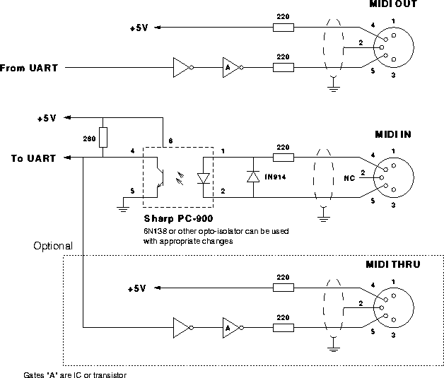
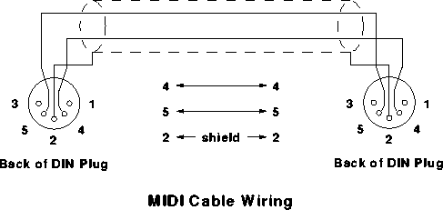
The MIDI Physical Layer
MIDI at the hardware level is very similar to RS-232. The key similarities are:
- both define hardware and protocol for serial data communication
- The MIDI data frame (1 start bit, 8 data bits, 1 stop bit) is a subset of the data frames allowed by RS-232
- both define a positive voltage/current to be a 'logical 0'.
A negative voltage is a 'logical 1' for RS-232 (note 1)
A zero current is a 'logical 1' for MIDI

The key differences are:
- RS232 defines a voltage swing +/- 5 to 15 V
MIDI defines a current swing 0 to 5 mA - RS232 has numerous standard baud rates 300,600...
MIDI has a single baud rate 31250 baud (note 2) - The MIDI standard requires that an opto-isolator be used on the receiver circuit
No isolation is required by RS-232 - RS-232 defines handshaking signals in addition to the data signals
MIDI does not use any handshaking signals - RS-232 uses a D25 connector
MIDI uses a 2x 5-pin DIN connectors


