¡¡[Transflective mode]
The transmissive
mode finds wide applications in LC displays, for instance desktop
monitor and LCD TV, because of its superior image quality. However
its usage is limited to indoor or low ambient lighting. The
reflective mode LCD owns the capability of outdoor using with decent
image quality. However due to the fact that the backlight is
lacking, it cannot be used indoor. To overcome both modes'
drawbacks, transflective mode is invented. It has two working modes:
transmission mode and reflection mode. Because its versatile
applications, it is widely used in portable devices like PDA, GPS
etc.
A simple transflective display
is shown in figure 1, in which there are two regions, T and R respectively. The
cell gap in two regions are different, dT = 2*dR. This is
to maintain the reflection and transmission from two regions are the same
intensity, and give same color reproduction, because in the T region, light only
goes through the LC layer once, while in the R region, light passes through
twice.
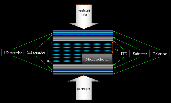
Figure 1. A
dual-cell-gap ECB transflective display, in which the cell gap in reflective
region dR is half of that in transmission region dT.
There are different types of
transflective displays, mainly four following:
1). Absorption type - it mainly
uses the Guest-Host mode to achieve the transflective mode, its working
principle is shown in figure 2.
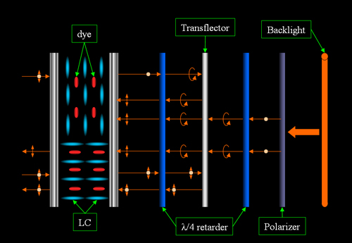
(a)
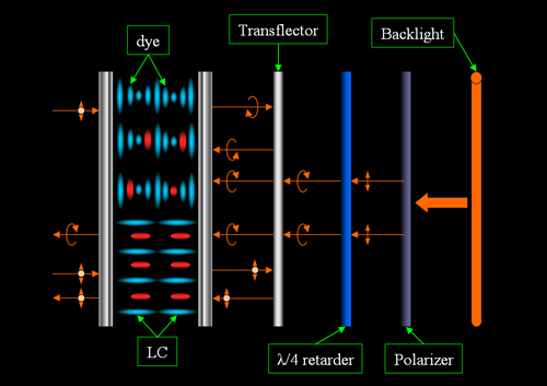
(b)
Figure 2.
Scattering type transflective display based on Guest-Host system (a) nematic LC
(b) cholesteric LC.
2). Reflection type - it
utilizes the Bragg reflection in cholesteric liquid crystal, its working
principle is shown in figure 3.
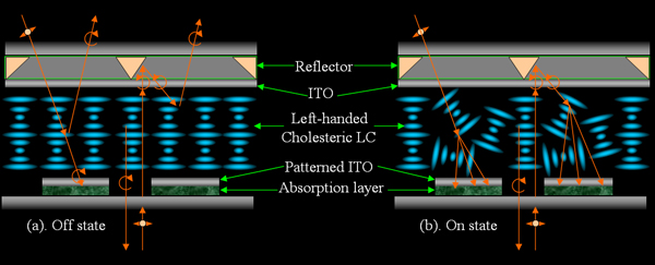
Figure 3.
A reflection type transflective display based on Bragg reflection in cholesteric
liquid crystals.
3). Scattering type - it relies
on the scattering in polymer dispersed liquid crystal, or polymer stabilized
liquid crystal, and therefore no polarizers are needed, which reduce the
manufacture cost. A polarizers required transflective display based on
scattering in liquid crystal gel was proposed by by Ren et al. The working
principle is shown in figure 4.
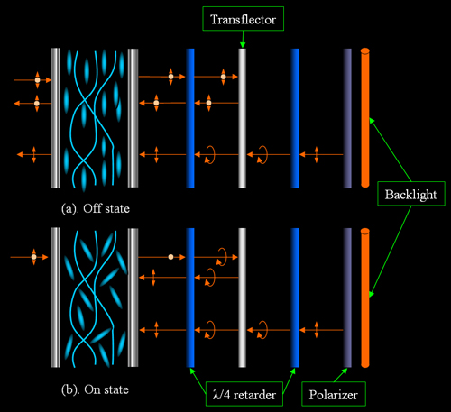
Figure 4.
A scattering type transflective display using
liquid crystals gels.
4). Phase retardation type -
this is the mostly used in current commercial transflective displays; different
LC modes can be used, for example, ECB, TN, MVA, IPS etc. Because the light is
modulated through changing its phase retardation, it is sensitive to the cell
gap, hence dual-cell-gap is introduced by Sharp to maintain the same phase
retardation both for T-region and R-region. Single cell gap mode is also
proposed, as shown in figure 1. The manufacture process of dual-cell-gap is more
complicated, and because of the gap difference, the response time in two regions
are different. Furthermore, the viewing angle of T-region is narrow because of
the polar tilt along the electric field.
Single-cell-gap transflective
devices are also proposed. The advantage of single-cell-gap structure ensures
the close dynamic response from both T- and R- region, resulting a more uniform
display. Figure 5 shows a single-cell-gap transflective mode based on employing
an image-enhanced reflector (IER). By using the IER, the aperture ratio can be
greatly improved.
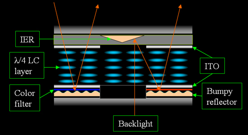
Figure 5. A
single-cell-gap transflective LCD based on an IER.
Further Readings
and References:
J. E. Bigelow,
¡°Transflective Liquid Crystal Display,¡± U.S. Patent 4 093 356, Jun.
6 (1978).
M. Okamoto, H.
Hiraki, and S. Mitsui, ¡°Liquid crystal display,¡± U.S. Patent 6 281
952, Aug. 28 (2001).
M. Shimizu, Y. Itoh,
and M. Kubo, ¡°Liquid crystal display device,¡± U.S. Patent 6 341 002,
Jan. 22 (2002).
Y. P. Huang, M. J.
Su, H. P. D. Shieh, and S. T. Wu, ¡°A single cell-gap transflective
color TFT-LCD by using image-enhanced reflector,¡± in SID Dig. Tech.
Papers, pp. 86¨C89 (2003).
Zhu, Z. Ge, T. X.
Wu, and S. -T. Wu, "Transflective Liquid Crystal Displays," J.
Display Technol. 1, 15- (2005).
¡¡